Mode settings
The final step before simulating is to choose the simulation mode (CTEM, STEM or CBED) and set the mode specific settings. Note that the active tab in the Mode panel decides the type of simulation that will be performed.
CTEM
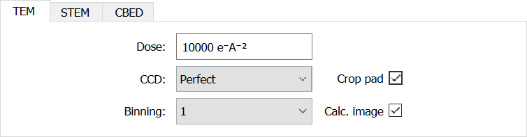
Figure The CTEM panel.
The CTEM specific settings are to set the CCD parameters, and to set the format of the outputs. On the left are 3 options that set the CCD simulation of the output image. These are the electron dose, the CCD name and the binning. This is then used to calculate an image based off the dose and detector detective quantum efficiency and noise transfer function. This provides a realistic approximation of the noise from an experimental image. Full details are provided in reference 9.
The other two options are the option to crop any padding from the output. This is purely for display/export, and the data for the cropped area is always calculated. Toggling this whilst displaying an existing simulation will show/hide the padded area without the need to re-simulate. The next check-box is to choose to calculate the image (as would be measured on a CCD, incorporating aberrations) or not. If this is unchecked, only the exit wave and diffraction pattern will be returned.
STEM
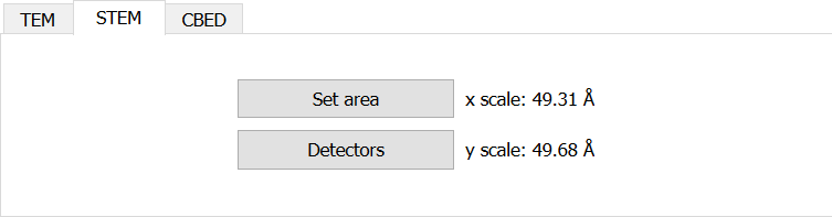
Figure The STEM panel.
The STEM frame provides a button to access the simulation area (as is accessible from the menu) but more importantly has a button to open the STEM detector dialog.
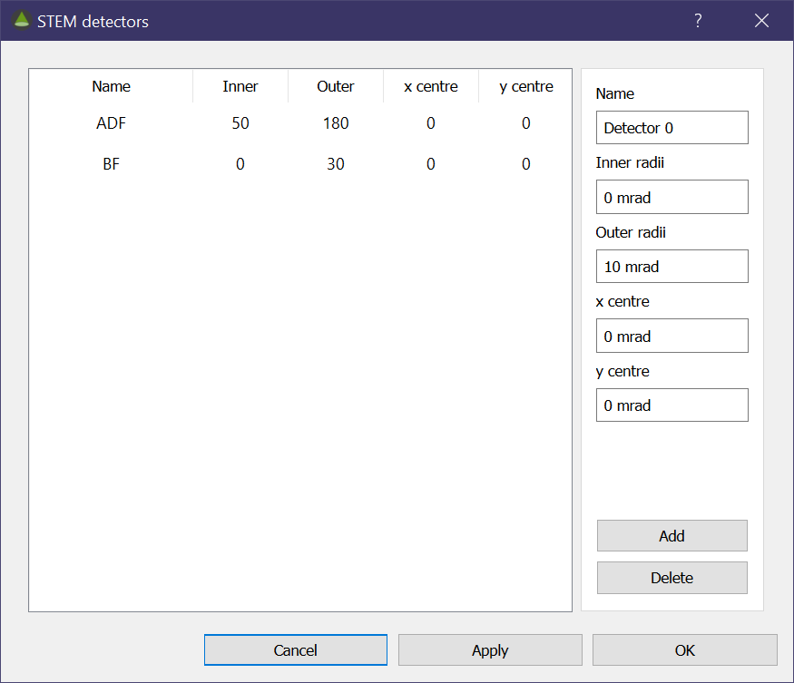
Figure Dialog used to set STEM detectors.
In the dialog you can set a detector with a name, inner and outer collection angles and even set an offset for the detector. Once these are set, you must click add and the detector will appear in the table on the left. This will also create a tab on the main interface Output panel to display the output image in.
CBED
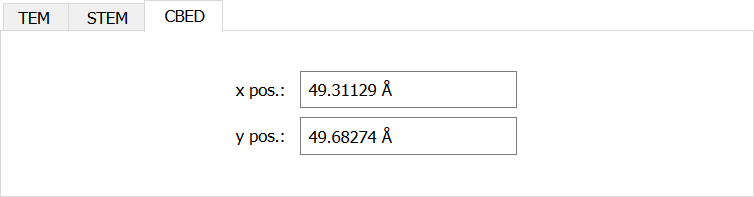
Figure The CBED panel.
the CBED frame has no special settings, though you can use it to quickly change the beam position without having to access the simulation are dialog.