Simulation area
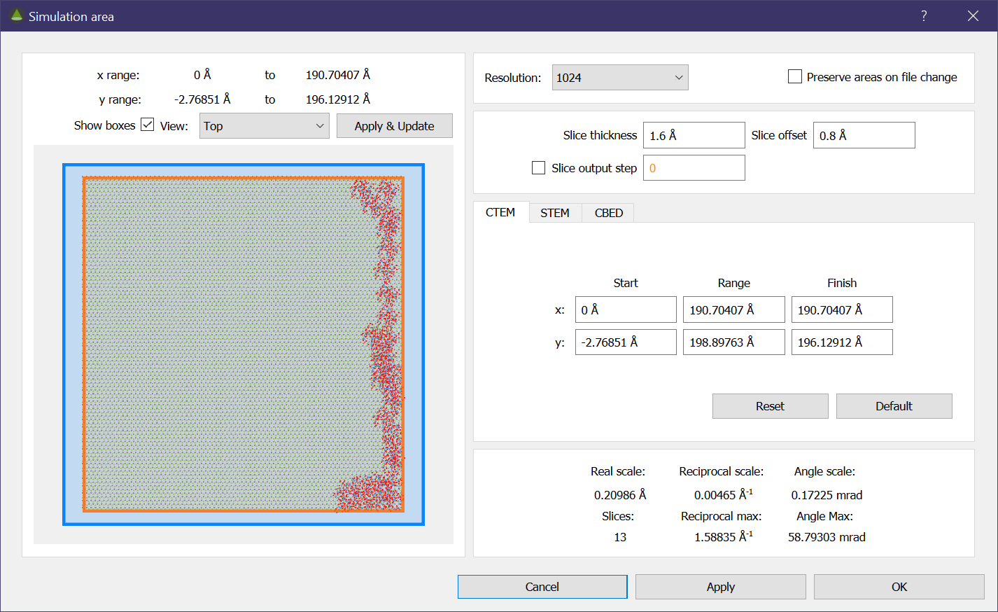
Figure The area options for the conventional TEM simulations. Note that the same range is applied to both x and y directions.
Opening the area dialog through the Simulation → Area menu or the Set area buttons allows you to set the area to be simulated as well as the slice configuration. The areas behave differently for each mode. At the bottom of the dialog, all the relevant scales and areas are shown. The simulation resolution can also be changed here to see how it affects the scales. There is also an option to preserve the simulation area when switching structure files (instead of defaulting to the entire structure). This can be toggled using the check-box in the top right.
Preview
The structure preview is shown on the left side along with the position range it occupies. An orange box is drawn to show the current simulation area selected using the panels on the right (this box will not be drawn for CBED). The blue box shows the area that will be calculated including the required padding. It is also possible to view the structure from the side, in which case the slices will be depicted by alternating yellow and blue boxes. Note that the preview is only updated after applying the changes
The preview is interactive and you are able to zoom by scrolling the mouse wheel, and you can left click and drag to pan around. The selection box above the preview can be used to set different view directions (with ‘Top’ being the view of the incident electron beam). The blue and orange boxes can also be hidden using the ‘Show boxes’ check-box.
Slices
Here you can set the slice thickness and slices offset. This is particularly important for the projected potentials, where it is best to set these two values so that planes of atoms lie in the middle of each slice. The slices in relation to the crystal structure can be seen in the preview.
There is also an option to output images at intermediate slice counts. This feature allows you to simulate a range of thickness with only a single multislice simulation. Note that this will increase the simulation time. The final output will always be retrieved alongside other outputs even if the final slice count is not a multiple of the intermediate output count.
TEM
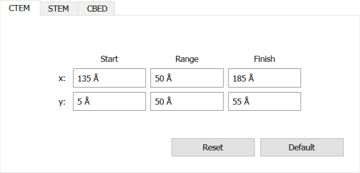
Figure The area options for the conventional TEM simulations. Note that the same range is applied to both x and y directions.
In TEM, the area is set very simply, defined by a start and finish position, but with a few caveats. Because the simulation relies on square FFTs, the simulation width and height must be the same. if you enter a different width and height, the simulation will pad to a square and you will have the options of cropping off the padded area if desired.
CBED
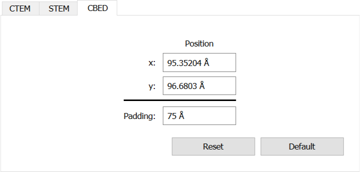
Figure The area options for the CBED simulations, note the extra padding option.
CBED simulation are only defined by the position of the probe. The padding is automatically added, though an extra padding option is available to adjust the scale in reciprocal space. For example, a CBED disc may only have a radius of 10 mrad, but the simulation scale may only achieve 5 mrad per pixel. This will create a lot of error in simulation the disc (i.e. try drawing a disc in a 4×4 pixel image). In this case, the padding can be increased so that the pixel resolution is smaller and a more accurate disc can be formed.
STEM
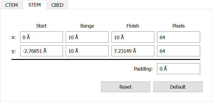
Figure The area options for the STEM simulations, the extra padding option behaves the same as in CBED.
In STEM mode, the scan parameters are defined very simply as a start/finish position as well as the number of pixels. This image is not directly affected by the simulation resolution (as opposed to the scan resolution), so can be any size you wish. The simulation resolution does affect the reciprocal resolution achieved. As an example, for annular dark field simulations a higher resolution may be needed to achieve the large collection angles. A padding option is provided, for the same reason as CBED.
If the parallel pixels optimisation is enabled, the simulation resolution is affected by the range of the scan.